![]()
![]()
Orthophoto Production
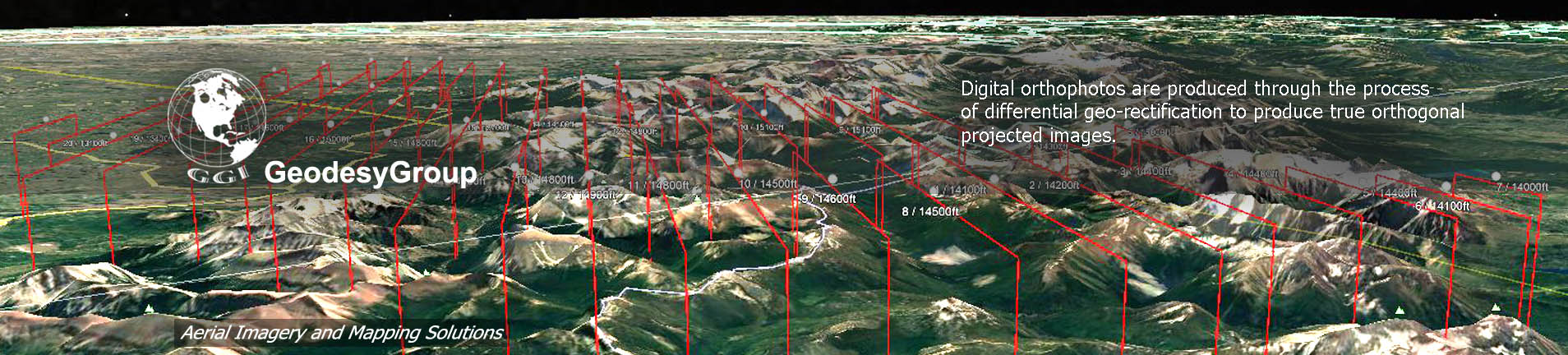
Digital orthophotos are produced through the process of differential geo-rectification to produce true orthogonal projected images. The process removes all distortions such as those caused by image perspective (tilt caused by the tip and roll of the aircraft) and relief (caused by terrain).Each image is “mapped” to the terrain using the exterior orientation parameters from the AT and the DEM using Inpho Orthomaster.
The centre (NADIR) area of each frame is used in the final ortho-mosaic. By doing this the amount of distortion in the final image is reduced and only that part of the image with the best radiometric quality is used. Images are tonally balanced and adaptive seam lines selected to ensure invisible joins between frames. Final mosaicing is conducted using Inpho OrthoVista to produce a completely seamless mosaic.
The final orthophoto tiles will be clipped out of the master image mosaic to fit the desired tiling scheme.
Final checks are performed on all orthophoto tiles to ensure that all required tiles have been produced (extent, pixel size, units, etc.) , are properly geo-referenced, are free of processing artifacts and are correctly named.
Aerial Triangulation (Method and Process)
We will use the direct geo-referencing data from the airborne GPS and IMU (inertial measurement unit) in conjunction with Automated Aerial Triangulation (AAT) for this project.Major advantages of this methodology are the ability to
· automate production processes and therefore reduce production times
· reduce ground control requirements
· improve accuracies
· substantially improve price compared to traditional AT.
The AAT will be perfomed using Inpho Match-AT software and the bundle block adjustment using Inpho inBlock. The computational output from the adjustment will provide statistics and an accuracy assessment of the AT on a model by model basis as well as creating the stereo model setups required for DEM observation and orthorectification.
The following steps describe each phase of the AT operation:
· Break up the project into manageble sized parts.
· Arrange the photos into strips and blocks for each part.
· Create the automatic tie points. Typically several hundred per image.
· Observe ground control points.
· Run initial AT computation using bundle block adjustment algorithm with robust blunder detection.
· Manually observe additional tie points in weak areas in the block and discard erroneous automatic tie points and blunders.
· Perform a least squares adjustment check on the block.
· Reduce tie points per image keeping only the strongest points. Typically results in about 100 points per image concentrated in the classic von Gruber positions.
· Perform final bundle block adjustment.
· Export results to stereo model setup.
A final report for the AT results will be prepared including the photogrammetric block layout and a diagram showing the location and names of all the points that were used in the adjustment. Results of the computations and an accuracy analysis of the final adjustment with respect to the project specifications will be documented.
The end result of the AT process is a set of adjusted co-ordinates and exterior orientations for every frame in the entire project. This information is used to properly orient the stereo models for DEM collection (if required) and for orthophoto generation.
![]() GeodseyGroup Inc. All Rights Reserved
GeodseyGroup Inc. All Rights Reserved